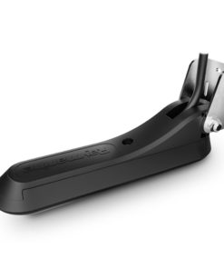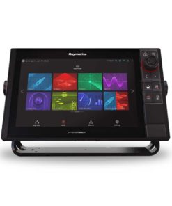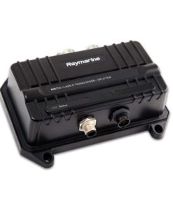

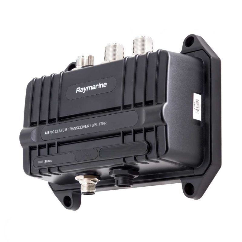
Raymarine AIS700 Class B Transceiver with Antenna Splitter
$ 1,286.59 excl. VAT
Compact and easy to install, the AIS700 Class B Transceiver is full transmit and receive device, built with an array of connecting options. Transmit your own vessels data as well as receive data from other vessels nearby, keeping you aware of what’s around you. A software and hardware enabled Silent Mode allows you to temporarily restrict the broadcasting of your vessels data while still receiving other vessels data, a significant feature where added security is needed, or even in competitive tournament scenarios when you might want to prevent others from finding out the location of the hot bite.
Note: Delivery time may take up to 1-2 weeks.
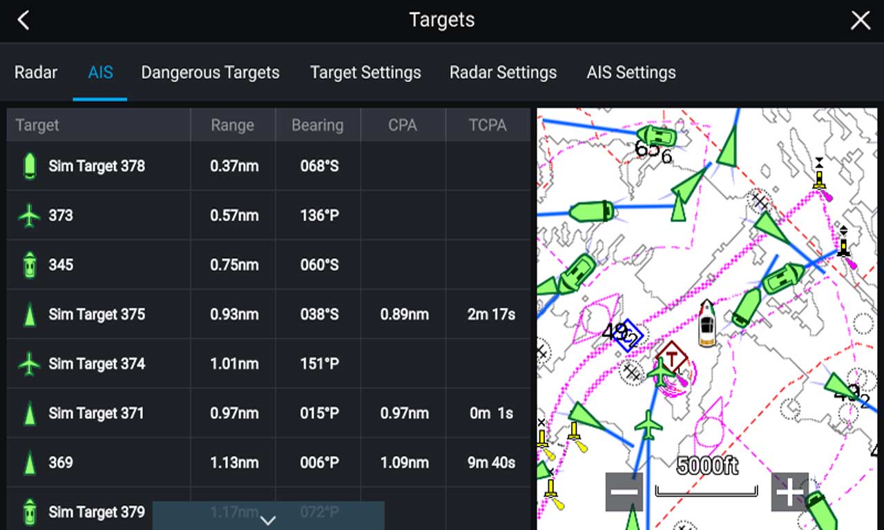
AIS Targets Menu
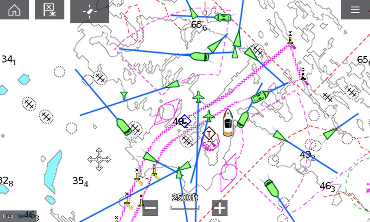
AIS Contacts
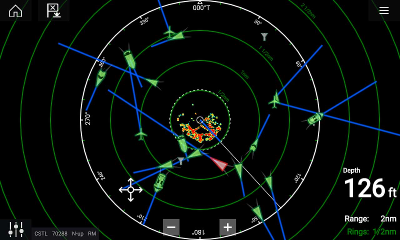
AIS Radar Overlay
Raymarine AIS700 Class B Transceiver features
- Full transmit and receive AIS for enhanced situational awareness and safety
- Latest SO-TDMA networking for longer range and faster performance
- Built-in antenna splitter simplifies installation with existing VHF radio antenna
- NMEA2000, NMEA0183, PC (setup & diagnostics) and SeaTalkng compatible
- Software or hardware switchable Silent Mode for enhanced security when needed
TECHNICAL DETAILS
MODEL | RAYMARINE AIS700 |
Environmental Specifications | |
Operating temperature | -15°C to +55°C |
Storage temperature | -20°C to +75°C |
Water ingress | IPX6 and IPX7 |
Humidity | Up to 93% @ 40°C |
Power Specifications | |
Power supply | 12v and 24 nominal |
Power consumption | <3W |
Peak current | 3A |
Load Equivalency Number | 1 LEN |
RF Specifications | |
DSC Receiver | Implemented by time sharing with one TDMA receiver |
Receiver 1 band | 156.025 MHz to 162.025 MHz (in 25KHz steps) |
Receiver 2 band | 156.025 MHz to 162.025 MHz (in 25KHz steps) |
Transmitter band | 156.025 MHz to 162.025 MHz (in 25KHz steps) |
Transmitter specification | To meet IEC 62287-2 relevant sections |
Receiver specification | To meet IEC 62287-2 relevant sections |
Transceiver specification | To meet IEC 62287-2 relevant sections |
GPS receiver | u-blox MAX-M8W |
GPS receiver channels | 72 channels |
GPS Cold start acquisition time | 26s nominal |
Positional source | GPS & GLONASS |
AIS performance | 5W SOTDMA |
Antenna Splitter Specifications | |
Operating frequency range | 156.0MHz to 162.025MHz Transmitting 156.0MHz to 162.025MHz Receiving |
Insertion loss AIS RX path | 0dB |
Insertion loss AIS TX path | <1dB |
Insertion loss VHF RX path | 0dB |
Insertion loss VHF TX path | <1dB |
Power handling AIS port | Maximum 5W input |
Power handling VHF port | 25W input |
Switching time RX to VHF TX | 10uS Max |
Switching time RX to AIS TX | 10uS Max |
Switching time VHF TX to AIS TX | 10uS Max |
Switching time any TX to RX | 10uS Max |
VHF port impedance | 50 Ohms |
AIS port impedance | 50 Ohms |
Antenna port impedance | 50 Ohms |
VHF to AIS port isolation | >28dB (both directions) |
Minimum VHF input power for switching | 400mW |
*To share a VHF antenna, the aerial should meet the following requirements (nominally tuned to 159MHz): | |
Frequency band | 156.025 MHz to 162.025 MHz |
VSWR (Voltage Standing Wave Radio) | Should not exceed 2:1 |
Impedance | 50 Ohm |
Gain | 3dBi Max |
Connector | PL-259 |
External Connections | |
VHF antenna connector type | SO-239 co-axial |
VHF radio connector type | SO-239 co-axial |
GNSS antenna connector | 50Ω TNC co-axial |
NMEA2000 | DeviceNet male |
USB | Micro-B |
External interface isolation | NMEA0183 and NMEA 2000 interfaces to incorporate galvanic isolation from power supply as required by the relevant interface specification. |
NMEA0183 interface 1 (MFD connection) | NMEA 0183 HS (IEC 61162-1) compliant, bi-directional, RS422 levels. 4 wire interface (differential signalling). Configurable baud rate. Input to MFD from AIS. |
NMEA0183 interface 2 (NMEA0183 instrument connection) | NMEA 0183 (IEC 61162-1) compliant, bi-directional, RS422 levels. 4 wire interface (differential signalling). 4 wire interface (differential signalling) Configurable baud rate |
USB interface (PC connection) | Protocol NMEA 0183 HS (IEC 61162-1) compliant, bi-directional USB port, 38.4 kBaud |